 RSS Feed
 Twitter
 Tuesday, December 14, 2010
 Designer
FPC Stands from Flexible Print Circuit.
Design data FPC,If CU making Negative then making Positive

CU negative data
1.Making one side FPC
Make a frame out according to the dimensions FPC
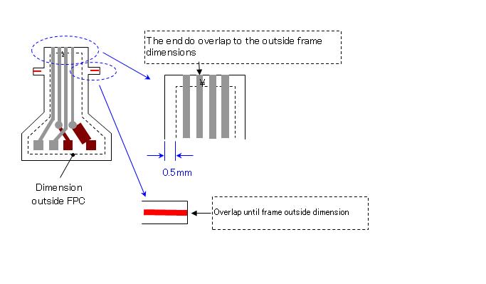
Make a frame out at Work Size, Then create a cavity FPC

Do not position the pattern more than 10 mm in circumference.

If the R data is then make the Print Range marker (Mark 十).
1.Parts NC

2.Parts the end of the FPC

3.Part of the work around

4.Guide pin and Marker print

Data NC / Throughole FPC
Because the NC data is a potential power CU front and Cu back then make a hole NC and markers print with (mark 十)

0 komentar:
Post a Comment